Steering (differential steering, rack & pinion
steering and front vs. rear wheel steering)
Selecting the proper type of steering is vital to the success of your robot because of the large impact it has on its maneuverability. The most common options are discussed below.
Differential steering is the most common type of steering used on robots today. It is also found on a variety of other mobile equipment, such as forklifts, tanks and wheelchairs. All of these mobile platforms share the need for maximized maneuverability.
A differentially steered or wheeled robot is comprised of two independently driven wheels on either side of the mobile platform that share a common axis of rotation. This type of steering can change direction by varying the relative velocity of the drive wheels and therefore does not require an additional steering mechanism. Figure 1 illustrates the path the two drive wheels take through a turn. In addition to its simplicity and ease of manufacturing, differential steering provides the greatest maneuverability out of the available steering options for this project.


Figure 1: Differential steering through a turn
Rack & pinion steering:
Most modern automobiles use rack and pinion steering for its precision, excellent driver feedback and longevity. As shown in figure 2, this type of steering is classified as Ackermann steering because of the relationship between the two steering wheels as the vehicle negotiates a turn. Specifically, rack and pinion steering derives its name from the type of gears used to generate the steering motion by converting rotational motion from the steering shaft into linear motion that pivots the vehicle’s wheels. Figure 3 shows a good illustration of the mechanism installed in a vehicle. Due to the precision nature of the rack and pinion gearset, this type of steering is expensive to manufacture; it’s also quite complex compared to other steering options.


Figure 2: Ackerman steering kinematics.

Figure 3: Rack & pinion mechanism.
Go kart steering:
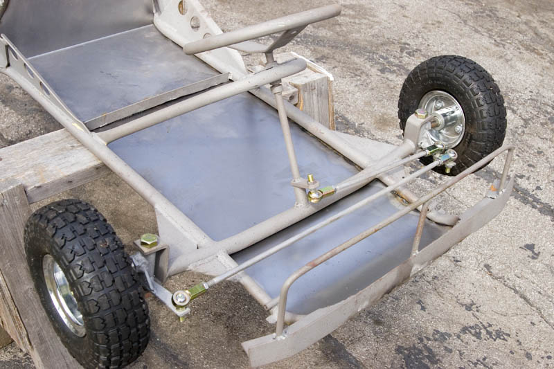
Go kart steering (as seen in figure 4 below) is another type of Ackermann steering that uses a simple crank-rocker instead of a more complex rack and pinion gear set to convert the rotational motion of the steering shaft into the linear motion that moves the wheels back and forth.

Figure 4: Go-kart style steering.
Front vs. rear wheel steering:
Consider now the difference between front and rear wheel steering. This refers to which “end” of the mobile platform the wheels that perform the steering function are attached. For maneuverability it is better to have the wheels closer to the item(s) being manipulated. This results in a shorter distance between the virtual pivot point of the vehicle and the item being manipulated. The advantage is increased sensitivity for the driver.
Turning radius or turning circle:
The turning radius or turning circle of a robot is the size of the smallest circular turn (i.e. U-turn) the robot is capable of making.
Two different
measurements can be quoted for a vehicle’s turning radius or turning
circle. A curb (or curb-to-curb) turning
circle indicates the distance traveled by the wheels. The wall (or wall-to-wall) turning
circle includes an allowance for the width of the whole vehicle, including the
overhang of the body structure. For
example, a robot might be quoted as having a turning circle (in inches) of
18.5(C)/22.5(W). It may be easier to
imagine that on a track with low curbs, you don’t need to consider anything
other than the wheels; however, if you were moving the robot inside an enclosed
area, the corners of the robot might hit the walls and the wall-to-wall turning
circle would need to be considered.
A notable exception in this description of turning radius or turning circle is of vehicles that possess differential steering and are thus capable of spinning around their central axis, such as a tank or certain lawnmowers. In this case the vehicle is said to have a "zero turning radius", although by the previous definition, it should be obvious this term is a gross misnomer. The vehicle still has a finite turning radius that is found as the linear distance between the virtual pivot axis (midway between the two drive wheels) and the outer-most point on the robot. [Source: Wikipedia]